First, a story. This project came in a dream, or rather the problem of how to do the base did. When we were newly married we had a Fiat 850 Spyder. It was one of the old school front end cars that had kingpins in the steering knuckles. They were notorious for not getting enough grease and grinding out the bushings resulting in a wobbly front end.
This occurred once on a trip to Texas to visit with Cathleen's parents and my father in law offered to put new kingpins in for me. During the repair he misplaced one or more of the caps that hold the grease in and after some cogitating went into the shop, came back with a big ball peen hammer and a couple of nickels. He used the ball end of the hammer and domed the nickels out to where they would fit into the kingpin mount, drilled holes and tapped for a zirk fitting to put grease in with, then pounded them into their respective places.
Somewhere is a Fiat with nickels in the front end still.
At any rate, the doming of the nickels showed up in a dream as applied to an old style mic stand and begged to be tried.
The photos show the process of the creation of one stand and boom attachment, mic and clip. Almost all parts function as full size, with the exceptions of mic, the knurled hand thing for tightening it when extending the stand, and friction holds the boom in lieu of a wingnut. I may try some more tiny screws and nuts later on, but friction seems to work well for now.
Should you decide to try this for yourself I offer the following info.
The lower section height is 3" (3 scale feet) from floor to top of the bottom tube. The upper tube is also 3", the boom is 2.5 to 3". The knurled hand screw thing in the middle is 1/4" tall.
The materials used are 1/8", 3/32", and 1/16" aluminum tubing, a nickel, a bit of ductwork aluminum sheet, a couple of short pieces of 1/32" brass tubing for rivets, a length of 1/4" aluminum bar stock, and some wire from a mouse cable.
Tools used include large ball peen hammer, hand sledge, various files, a jeweler's lathe (which could be replaced by a drill press to spin things), and both thick and medium super glue and if you are brave, some super glue kicker spray - keep it away from the glue bottles, and wash your hands before you attempt any further gluing or you may find yourself more than emotionally attached to your project.
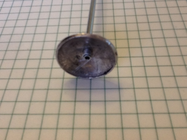
 The nickel is glued to a piece of wood and pressed in a bit in a vise. The exposed side is then filed flat and rough polished. A centered hole is drilled and the blank removed from the wood. I initially used the hard rubber block pictured to beat against, but have since moved to a piece of wood soft enough that I can dome a nickel in one bash. The nickel is placed shiny side down, the ball end of the ball peen hammer is centered on it and struck a mighty blow with the hand sledge. If all was correct, the domed nickel will be centered nicely and shaped like a mic stand base.


 |
If the hole deformed during the striking, it is reamed to fit the tube.
It gets sanded smooth with various grits of paper, then placed in a hand vise for polishing against a tripoli loaded buffing wheel. |
|

 |
At this point the base is glued to the sleeve and the lower pole with gel superglue.
|


This completes the lower portion of the stand,
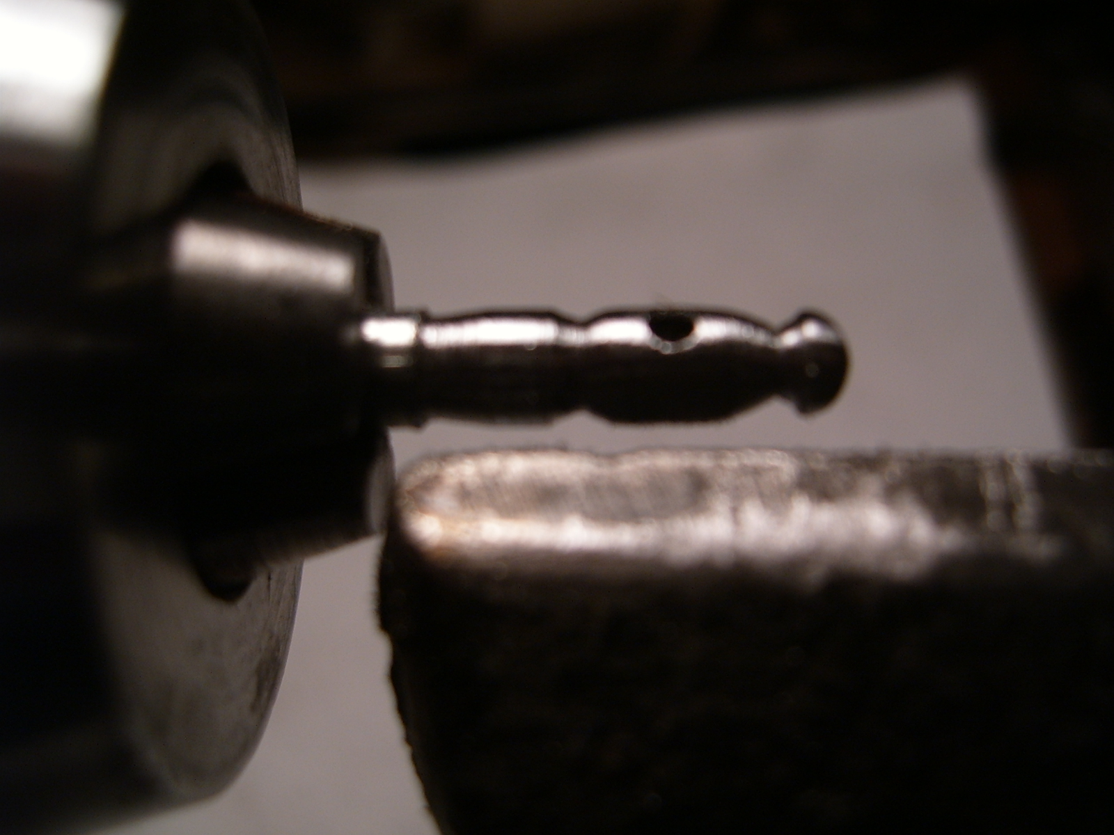
The boom mount comes next, but I will show rather than try to describe it. It involves filing away everything from a length of 1/4" diam aluminum bar stock that does not look like a boom mount.
The hinge pins are 1/32" hollow brass tubing with the ends flared and clamped flat, which also imparts the required friction for movement.
 |
| Test fitting prior to parting off the base. |
|
|
 |
Boring out the bottom of the bottom boom mount piece
 |
Boom assembly after riveting.
|
|
 |
| Boring out the counterweight |
 |
| The mic cable is a wire from a mouse cable, the XLR plugs were turned from 1/16" diam aluminum tubing. |
The mic clip is of sheet aluminum and tubing as in the photo, hinge pin again being 1/32" brass tubing flared on the ends and flattened..
The mics are nested tubing filed down to taper in the lathe, then painted. The vocal mics are still in design stage as just turning a ball and either painting the screen lines, scoring the screen lines in a painted ball, or just scoring the ball are not convincing to me. I am attempting to fashion screen balls from fine mesh screen and will update this series when successful and complete.


